- Home
- Cable Glands
- Products
- Adaptors / Reducers
- 737 | Thread Conversions | Adaptors & Reducers
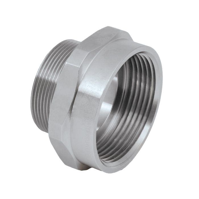 737 Adaptor
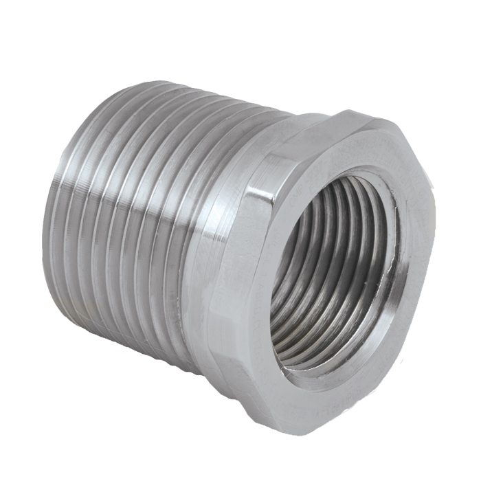 737 Reducer
- Ex ta
737 | Thread Conversions | Adaptors & Reducers Available in nickel plated brass, brass, nylon, stainless steel, aluminium
We'd like to keep in touch
We have some exciting things in the pipeline - if you'd like to be the first to know please enter your email address below.
737 Adaptors/ Adapters & Reducers for a Wide Range of Thread Sizes and Types
Adaptors/Adapters & Reducers, Globally Approved, Explosive Atmosphere Cable / Conduit Accessory
- Used for thread conversion
- Wide range of thread types & sizes
- General purpose / industrial version available
- Equipment interface ‘O’ ring seal available
- -60°C to +200°C (metallic versions)
- Reducers Globally marked: – IECEx, ATEX, UL, cCSAus & UKEX
- Adaptors Globally marked: – Up to 2 steps up in size IECEx, ATEX, cCSAus, UKEX
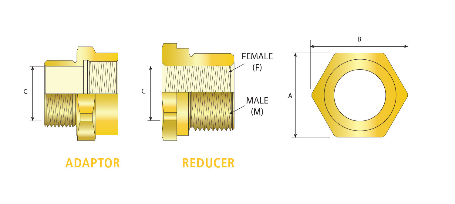
In order to select and adaptor/adapters & reducers, using the below dimension tables:
1 ) Select male thread from the left hand column of Table ‘A’
2) Select the female thread size from the top of Table ‘A’, referenced ‘A**’ for adaptor/adapter and ‘R**’ for reducer
3) Using this code reference, please refer to the corresponding dimensions in Table ‘B’
Please contact us if you require assistance with selecting the correct adaptor/adapters & reducers.
| Design Specification | BS 6121:Part 1:1989, IEC 62444, EN 62444 |
| Enclosure Protection | IK10 to IEC 62262 (20 joules) Brass & Stainless Steel Only |
| ATEX Certificate | CML 18ATEX1320X |
| UKEX Certificate | CML 21UKEX1238X |
| Code of Protection | II 2G Ex db IIC Gb, Ex eb IIC Gb, II 1D Ex ta IIIC Da IM2 Ex db I Mb, Ex eb I Mb (II 2G Ex eb IIC Gb, II 1D Ex ta IIIC Da only on Nylon version) |
| Compliance Standards | EN 60079-0,1,7,31 |
| IECEx Certificate | IECEx CML 18.0177X, IECEx SIM 15.0002X |
| Code of Protection | Ex db I Mb, Ex eb I Mb, Ex d IIC Gb, Ex eb IIC Gb, Ex ta IIIC Da (Ex eb IIC Gb , Ex ta IIIC Da only on nylon version) |
| Compliance Standards | IEC 60079-0,1,7,31 |
| cCSAus Certificate | 1055233 |
| Code of Protection | Class I, Groups A, B, C and D; IP66, 67, 68; Enclosure Type 4X; Class II groups E, F and G; Class III, Ex de II, Class I, Zone 1, AEx de II; (Not available in Nylon) |
| Compliance Standards | C22.2 No.0, 0.5, 30, 94,CAN/CSA E60079-0,1, 7, CAN-CSA E61241-1, UL50 Edition 11, UL1203 Edition 4, UL 60079-0,1,7 |
| UL Certificate | E214221 (Reducers with NPT or Metric Threads only) |
| Code of Protection | Class I Groups A,B,C,D; Class II Groups E,F,G; Class III |
| Compliance Standards | UL 1203 |
| EAC Certificate | C-GB.A07.B.02500/20 |
| GOST R Certificate | POCC.GB.HA46.H00140 |
| KCs Certificate | 14-GA4BO-0249X |
| CCOE / PESO (India) Certificate | Ex d: P548696, Ex e: P533772 |
| CCC Certificate | 2020322313003177 |
| Compliance Standards | GB3836.1, 2, 3 |
| INMETRO Approval | TÜV 12.1332X |
| RETIE Approval | 03866 |
| UkrSEPRO | CU 19.0372X |
| SANS | MS-XPL21804 21.0006X |
| Marine Approvals | LRS: 01/00173, ABS: 17-LD1619350-PDA, BV: 43180/A1 BV 17-LD1619350-PDA |
| Continuous Operating Temperature | -60°C to +200°C (Metallic), -20°C to +60°C (Nylon) |
| Ingress Protection Rating ** | IP66, IP67 & IP68 (when fitted with CMP sealing accessories) |
| Available Materials | Electroless Nickel Plated Brass, Brass, Nylon, Stainless Steel, Aluminium |
| ECAS Certificate | 24-03-106290/E24-03-110155/NB0007 |
** Refer to Maintaining a Seal for further information on Ingress Protection Ratings
Certificates


| TABLE A - MALE THREAD SIZE | TABLE A - FEMALE THREAD SIZE | ||||||||||||||||||||||
| METRIC | NPT | ||||||||||||||||||||||
| METRIC | M16 | M20 | M25 | M32 | M40 | M50 | M63 | M75 | M90 | M100 | ½" | ¾" | 1" | 1¼" | 1½" | 2" | 2½" | 3" | 3½" | 4" | |||
| M16 | A01 | A04 | A08 | A03 | A08 | ||||||||||||||||||
| M20 | R01 | A05 | A07 | A12 | A05 | A11 | A15 | ||||||||||||||||
| M25 | R05 | R03 | A09 | A14 | A18 | R03 | A09 | A16 | A18 | ||||||||||||||
| M32 | R06 | R06 | R06 | A17 | A19 | A24 | R06 | R06 | A17 | A19 | A24 | ||||||||||||
| M40 | R08 | R08 | R08 | R08 | A20 | A29 | A33 | R08 | R08 | R08 | A21 | A25 | A33 | ||||||||||
| M50 | R10 | R10 | R10 | R10 | R10 | A28 | A35 | A49 | R11 | R11 | R10 | R10 | A27 | A32 | A42 | A52 | |||||||
| M63 | R12 | R12 | R12 | R12 | R12 | A37 | A48 | A53 | R12 | R12 | R12 | R12 | R12 | A37 | A44 | A53 | |||||||
| M75 | R14 | R14 | R14 | R14 | R16 | R15 | A47 | A55 | A57 | R14 | R14 | R14 | R14 | R14 | A46 | A55 | A61 | ||||||
| M90 | R19 | R19 | R17 | R19 | A60 | R18 | |||||||||||||||||
| M100 | R20 | R20 | R20 | A58 | |||||||||||||||||||
| NPT | ½" | R02 | A06 | A07 | A12 | A02 | A10 | A15 | |||||||||||||||
| ¾" | R04 | R04 | A09 | A16 | A22 | R04 | A09 | A16 | A18 | ||||||||||||||
| 1" | R07 | R07 | R07 | A13 | A19 | R07 | R07 | A17 | A19 | A24 | |||||||||||||
| 1¼" | R09 | R09 | R09 | R09 | A20 | A23 | R09 | R09 | R09 | A20 | A25 | A30 | |||||||||||
| 1½" | R10 | R10 | R10 | R11 | A26 | A34 | R10 | R10 | R10 | R10 | A26 | A31 | A41 | ||||||||||
| 2" | R12 | R12 | R12 | R12 | R12 | A36 | A43 | R12 | R12 | R12 | R12 | R12 | A39 | A50 | |||||||||
| 2½" | R14 | R14 | R14 | R14 | R13 | R13 | A40 | R14 | R14 | R14 | R14 | R14 | R14 | A45 | A54 | ||||||||
| 3" | R17 | R19 | R19 | R18 | R19 | R19 | A56 | R17 | R18 | R18 | R18 | R18 | R19 | A51 | A59 | A62 | |||||||
| 3½" | R17 | R20 | R20 | R20 | R20 | R20 | R20 | R20 | R20 | R20 | R20 | ||||||||||||
| 4" | R21 | R21 | R21 | R21 | R21 | R21 | R21 | R21 | R21 | ||||||||||||||
| TABLE B - REDUCERS | TABLE B - ADAPTORS | ||||||||||||||||||||||
| Table A Ref. | Across Flats 'A' | Across Corners 'B' | Table A Ref. | Across Flats 'A' | Across Corners 'B' | Minimum Bore 'C' | Table A Ref. | Across Flats 'A' | Across Corners 'B' | Minimum Bore 'C' | Table A Ref. | Across Flats 'A' | Across Corners 'B' | Minimum Bore 'C' | |||||||||
| R01 | 24.0 | 26.4 | A01 | 22.0 | 24.2 | 9.7 | A23 | 55.0 | 60.5 | 32.1 | A45 | 80.0 | 88.0 | 60.5 | |||||||||
| R02 | 27.0 | 29.7 | A02 | 24.0 | 26.4 | 14.0 | A24 | 55.0 | 60.5 | 26.0 | A46 | 80.0 | 88.0 | 65.0 | |||||||||
| R03 | 30.0 | 33.0 | A03 | 24.0 | 26.4 | 9.7 | A25 | 55.0 | 60.5 | 32.0 | A47 | 84.0 | 92.4 | 68.0 | |||||||||
| R04 | 31.5 | 34.7 | A04 | 24.0 | 26.4 | 10.0 | A26 | 55.0 | 60.5 | 38.0 | A48 | 90.2 | 99.2 | 53.0 | |||||||||
| R05 | 31.5 | 34.7 | A05 | 24.0 | 26.4 | 14.0 | A27 | 55.0 | 60.5 | 43.6 | A49 | 90.2 | 99.2 | 42.0 | |||||||||
| R06 | 37.6 | 41.4 | A06 | 27.0 | 29.7 | 14.0 | A28 | 59.8 | 65.8 | 44.2 | A50 | 95.0 | 104.5 | 49.0 | |||||||||
| R07 | 41.0 | 45.1 | A07 | 30.0 | 33.0 | 14.0 | A29 | 60.0 | 66.0 | 32.1 | A51 | 95.0 | 104.5 | 75.0 | |||||||||
| R08 | 46.0 | 50.6 | A08 | 30.0 | 33.0 | 9.7 | A30 | 65.0 | 71.5 | 32.0 | A52 | 100.0 | 110.0 | 44.2 | |||||||||
| R09 | 50.0 | 55.0 | A09 | 30.0 | 33.0 | 20.0 | A31 | 65.0 | 71.5 | 38.0 | A53 | 100.0 | 110.0 | 55.0 | |||||||||
| R10 | 55.0 | 60.5 | A10 | 30.5 | 33.6 | 14.0 | A32 | 65.0 | 71.5 | 44.2 | A54 | 100.0 | 110.0 | 60.5 | |||||||||
| R11 | 60.0 | 66.0 | A11 | 31.5 | 34.7 | 14.0 | A33 | 70.0 | 77.0 | 32.0 | A55 | 100.0 | 110.0 | 64.8 | |||||||||
| R12 | 70.0 | 77.0 | A12 | 36.0 | 39.6 | 14.0 | A34 | 70.0 | 77.0 | 38.0 | A56 | 100.0 | 110.0 | 75.0 | |||||||||
| R13 | 79.0 | 86.9 | A13 | 36.0 | 39.6 | 26.0 | A35 | 70.0 | 77.0 | 44.2 | A57 | 110.0 | 121.0 | 61.0 | |||||||||
| R14 | 80.0 | 88.0 | A14 | 37.6 | 41.4 | 20.0 | A36 | 70.0 | 77.0 | 49.0 | A58 | 110.0 | 121.0 | 75.0 | |||||||||
| R15 | 84.0 | 92.4 | A15 | 41.0 | 45.1 | 14.0 | A37 | 70.0 | 77.0 | 53.0 | A59 | 110.0 | 121.0 | 75.0 | |||||||||
| R16 | 90.2 | 99.2 | A16 | 41.0 | 45.1 | 20.0 | A38 | 70.0 | 77.0 | 32.1 | A60 | 110.0 | 121.0 | 79.3 | |||||||||
| R17 | 95.0 | 104.5 | A17 | 41.0 | 45.1 | 26.0 | A39 | 79.0 | 86.9 | 49.0 | A61 | 110.0 | 121.0 | 68.3 | |||||||||
| R18 | 98.8 | 108.7 | A18 | 46.0 | 50.6 | 20.0 | A40 | 79.0 | 86.9 | 60.0 | A62 | 117.5 | 129.3 | 75.0 | |||||||||
| R19 | 100.0 | 110.0 | A19 | 46.0 | 50.6 | 26.0 | A41 | 80.0 | 88.0 | 38.0 | |||||||||||||
| R20 | 110.0 | 121.0 | A20 | 46.0 | 50.6 | 32.1 | A42 | 80.0 | 88.0 | 44.2 | |||||||||||||
| R21 | 123.0 | 135.3 | A21 | 50.0 | 55.0 | 32.0 | A43 | 80.0 | 88.0 | 49.0 | |||||||||||||
| R22 | 127.0 | 139.7 | A22 | 50.0 | 55.0 | 20.0 | A44 | 80.0 | 88.0 | 55.0 | |||||||||||||
| Additional sizes available upon request |
|||||||||||||||||||||||
| Minimum reducer bore determined by female thread | |||||||||||||||||||||||
| Dimensions displayed in millimetres | |||||||||||||||||||||||
The Use of Multiple Adaptors in a Single Entry for Ex Equipment
The IEC 60079-1 standard allows the use of threaded adaptors and reducers for direct entry into Flameproof type ‘d’ enclosures. In future, the female connection threads of the adaptors and/or reducers will be limited to metric or NPT only. When using thread adaptors and reducers or reducer bushings, only one is permitted for any single cable entry of Flameproof type ‘d’ (Ex d) equipment.
Read moreCable Entries Made Directly into Flameproof Type ‘d’ (Ex d)
The following page contains an illustrative example of Cable Entries Made Directly into Flameproof Type 'd' (Ex d).
Read moreTypical Installation Configurations
The illustrations provided below are indicative of some of the common methods of installation configurations adopted. These are for informative guidance only and relevant site conditions along with any specified National or International codes of practice must always take precedence. The accessories available offer a wide, flexible approach in mounting, sealing and earthing connection provision. Selection and installation according to the Engineering Specification may vary from these illustrations.
Read moreVisit our Knowledge Base for technical expertise and advice, gathered over CMP's 60+ years' experience in the art of terminating cable glands.
Sign up now