- Home
- Cable Glands
- Products
- Adaptors / Reducers
- 783 | Dual Entry Y Adaptor
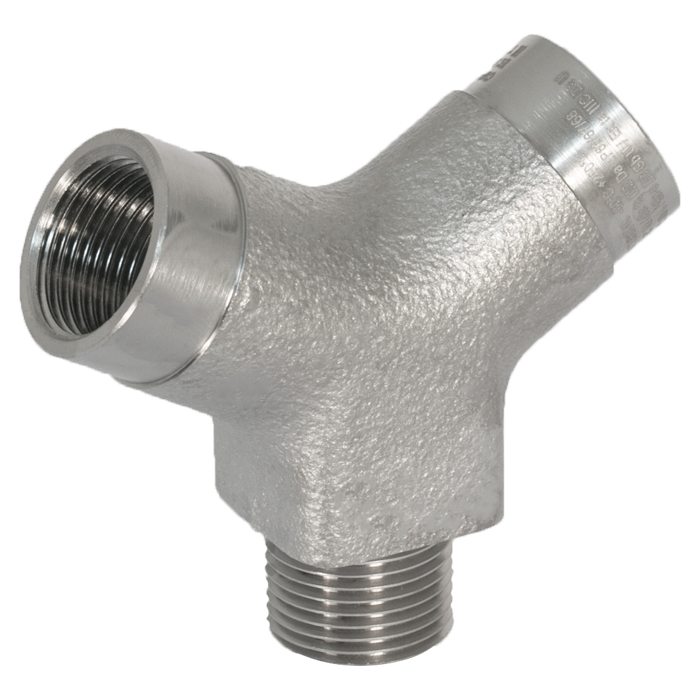
783 | Dual Entry Y Adaptor Available in brass, nickel plated brass, stainless steel
We'd like to keep in touch
We have some exciting things in the pipeline - if you'd like to be the first to know please enter your email address below.
Internationally Approved, Explosive Atmosphere Cable / Conduit Accessory
• Provides an opportunity for two entries
• As standard one male & two female entries
• Supplied with male or female threads upon request
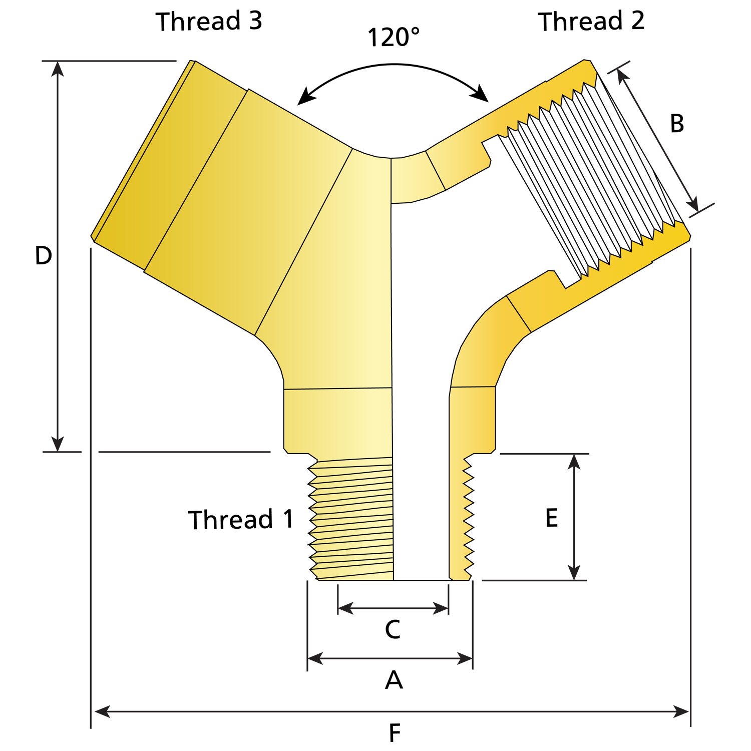
• All angles 120°
• Protects cables from excessive bending stress
• General purpose / industrial version available
• Can be supplied with thread conversion upon request
• -60°C to +200°C
• Globally marked, IECEx, ATEX & EAC (TC RU)
• Can be used with 737 (not Ex d direct entry applications)
| Design Specification | BS 6121:Part 1:1989, IEC 62444, EN 62444 |
| Enclosure Protection | IK10 to IEC 62262 (20 joules) Brass & Stainless Steel Only |
| ATEX Certificate | CML 18ATEX1306U |
| UKEX Certificate | CML 21UKEX1216U |
| Code of Protection | II 2G Ex db IIC Gb, Ex eb IIC Gb, II 1D Ex ta IIIC Da IM2 Ex db I Mb, Ex eb I Mb |
| Compliance Standards | EN 60079-0,1,7,31 |
| IECEx Certificate | IECEx CML 18.0171U |
| UkrSEPRO | CU 19.0370X |
| CCOE / PESO (India) Certificate | Ex d: P548696, Ex e: P533772 |
| Code of Protection | Ex db IIC Gb, Ex eb IIC Gb, Ex ta IIIC Da Ex db I Mb, Ex eb I Mb |
| Compliance Standards | IEC 60079-0,1,7,31 |
| EAC Certificate (Formerly GOST R, K & B) | C-GB.A07.B.02491/20 |
| Ingress Protection Rating ** | IP66, IP67 & IP68 (when fitted with CMP sealing accessories) |
| Available Materials | Brass, Electroless Nickel Plated Brass, Stainless Steel |
| NEPSI Certificate | GYJ18.1258U |
| ECAS Certificate | 24-03-106290/E24-03-110155/NB0007 |
HOW TO ORDER
e.g. 783 - D - M - 2 - M - M - 2 - F - M - 2 - F - 5
= Dual Certified Ex d & Ex e - M20 (M) x M20 (F) x M20 (F) - Nickel Plated Brass
* Any combination of Male (M) / Female (F) threads is available e.g.
(M) X (M) X (M), (F) X (F) X (F), (M) X (F) X (M)
Marked with ATEX, IECEx and EAC (TC RU) certification details as standard
Other thread variations are available upon request
Please refer to ordering guide tables in ‘Ordering Accessories’ for further information
Certificates
Product Selection Table
| Ordering Reference | Bore Diameter 'C' | Thread 1 'A' (Entry Thread) | Thread 2 'B' | Thread 3 'B' | Thread Length 'E' | Protrusion Length 'D' | Protrusion Length 'F' | Width |
| 783DM2MM2FM2F | 0.58 | M20 | M20 | M20 | 0.59 | 1.89 | 2.87 | 0.98 - 1.06 |
| 783DT1MT1FT1F | 0.58 | 1/2' NPT | 1/2' NPT | 1/2' NPT | 0.78 | 1.69 | 2.87 | 0.98 - 1.06 |
| 783DM3MM3FM3F | 0.74 | M25 | M25 | M25 | 0.59 | 1.89 | 3.03 | 1.18 - 1.26 |
| 783DT2MT2FT2F | 0.74 | 3/4" NPT | 3/4" NPT | 3/4" NPT | 0.80 | 1.89 | 3.03 | 1.18 - 1.26 |
| 783DM4MM4FM4F | 1.02 | M32 | M32 | M32 | 0.59 | 2.22 | 3.64 | 1.46 - 1.54 |
| 783DT3MT3FT3F | 1.02 | 1" NPT | 1" NPT | 1" NPT | 0.98 | 2.22 | 3.64 | 1.46 - 1.54 |
| All dimensions shown are in inches unless otherwise stated | ||||||||
| Ordering Reference | Bore Diameter 'C' | Thread 1 'A' (Entry Thread) | Thread 2 B | Thread 3 'B' | Thread Length 'E' | Protrusion Length 'D' | Protrusion Length 'F' | Width |
| 783DM2MM2FM2F | 14.7 | M20 | M20 | M20 | 15.0 | 48.0 | 73.0 | 25 - 27 |
| 783DT1MT1FT1F | 14.7 | 1/2' NPT | 1/2' NPT | 1/2' NPT | 19.9 | 43.0 | 73.0 | 25 - 27 |
| 783DM3MM3FM3F | 18.9 | M25 | M25 | M25 | 15.0 | 48.0 | 76.9 | 30 - 32 |
| 783DT2MT2FT2F | 18.9 | 3/4" NPT | 3/4" NPT | 3/4" NPT | 20.2 | 48.0 | 76.9 | 30 - 32 |
| 783DM4MM4FM4F | 25.9 | M32 | M32 | M32 | 15.0 | 56.5 | 92.5 | 37 - 39 |
| 783DT3MT3FT3F | 25.9 | 1" NPT | 1" NPT | 1" NPT | 25.0 | 56.5 | 92.5 | 37 - 39 |
| All dimensions shown are in millimetres unless otherwise stated | ||||||||
Cable Gland Material Selection
There are numerous different grades of materials used for the production of cable glands by different manufacturers and it is important to identify the precise grades used before proper and effective evaluation can be achieved. Given the range of potential environments, including indoor and outdoor, the compatibility and the selection of material used in the production of cable glands is very important.
Read moreThe Use of Multiple Adaptors in a Single Entry for Ex Equipment
The IEC 60079-1 standard allows the use of threaded adaptors and reducers for direct entry into Flameproof type ‘d’ enclosures. In future, the female connection threads of the adaptors and/or reducers will be limited to metric or NPT only. When using thread adaptors and reducers or reducer bushings, only one is permitted for any single cable entry of Flameproof type ‘d’ (Ex d) equipment.
Read moreInstallation Accessories
Depending upon the specific form of protection of the main equipment it may be necessary (and often advisable) to fit a sealing washer at the cable entry interface to maintain the appropriate Ingress Protection level of the enclosure. For Increased Safety (Ex e) equipment, or Increased Safety terminal chambers included in Ex de (or Ex db eb) equipment, a sealing washer is recommended to maintain the minimum ingress protection rating, and should always be fitted.
Read moreVisit our Knowledge Base for technical expertise and advice, gathered over CMP's 60+ years' experience in the art of terminating cable glands.
Sign up now


